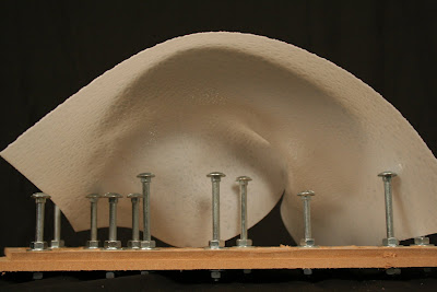
The holes for the press plates are drilled in symmetry about the center. Meaning, for the six holes for each grove only three holes need to be alignment on the drill press. Each time a hole is aligned on the drill press, two rows of holes can be obtained on the plates by rotating the formwork.
Recap: for the four rows of holes away from center, the clamps are repositioned, and additional height on the jig is added to accomodate the clamps' new position as not to conflict with the formwork.
The added height for the jig only applies for the outer four rows, which means only two holes on the jig, given the formwork's plate can be rotated given the symmetrical nature of the holes about the long axis.
Structural support is then added to the base of the plates to prevent the now perforated surface from breaking under its own weight. Dense wood for molding is used, and the sectional dimension of the supports are determined by the clearance from the washers and nuts (when the bolts are installed).
Six rows of holes per plate. A lot of carriage bolts are yet to be installed. Given the added bracing for the MDF plates, hopefully the dense wood bars will also support the 228 carriage bolts, 456 washers and 456 nuts (calculated at thirty-eight groves and six holes per grove for each plate). Again, washers and nuts are needed to keep the bolts in an orthogonal position, as the holes themselves do not bear enough depth or thread to maintain the bolts' verticality.
Thursday, May 15, 2008
Formwork Documentation: The Holes (Part 1)
Pilots are required for the bolts. Based on previous investigation, one-inch centering of the holes would be pushing the (pseudo-laminated) MDF boards to a point of breaking. And holes are offset from the very edge to prevent tearing. Finally, six holes per grove are set to be drilled at 1-1/8 inch O.C.
For standardization and alignment of the holes, a base (or jig) is built to both support the plates and ensure a clean hole (by prevent the underside of the plate from "breaking" as the drill bit is pushing through).
Three bars are raised from the jig to set for the plates' groves to improve alignment.
A fence in the back is set to align the press plate when it is moved from grove to grove.
Notice the jig has been slightly built up (by 1/4") to accomodate the new position of the clamps. After drilling the center two rows, the jig had to be re-aligned for the next two rows from the center, and the original position for the clamps can no longer accomodate the elongated reach. Hence, clamps have been moved to the sides of the jig.
First four center rows are drilled. End rows along the edges are yet to come.
Tripod legs are used to support the ends of the plates to prevent over-cantilevering.
Formwork Documentation: Beginning
The two events from the movie clip have been translated into panels. The intent is for the two panels to face each other and "converge" (or press into each other) and become something like an iron maiden. The dog chase is represented by one plate and the the mob chase is the other.
Click below for past blog posts on
Generating Move Clip and Associated Analyses
The two formworks will compress one panel in between and generate a surface. The deformations in the surface will be determined by the diagrammatic elements of each transition. Bolts of different lengths set in in different combinations will translate the compositional smoothness of the transitions.
Dimensions for plates are determined by means of material availability and means of available transportation. It is true the formwork should be "large" within reasonable parameters.
Surface Generation: Materiality Tests 05
Surface Generation: Materiality Tests 04
Surface Generation: Materiality Tests 03
Surface Generation: Materiality Tests 02
Subscribe to:
Posts (Atom)